Introduction
Building a mobile robot is the ultimate hands-on way to apply robotics concepts, integrating sensors, actuators, controllers, and programming. It allows learners to experience the full robotics development lifecycle, from hardware assembly to algorithmic control.
At Curiosity Tech, learners can access step-by-step tutorials, simulation guides, and real-world project tips to successfully build and test their first robot, bridging theory and practical expertise.
1. Project Overview
Objective: Build a simple mobile robot capable of moving, detecting obstacles, and following a line or path.
Key Learning Outcomes:
- Understanding robot chassis design.
- Integrating motors and motor drivers.
- Implementing sensor interfacing.
- Programming movement logic using microcontrollers.
- Testing and debugging real-world robot behavior.
2. Components Required
| Component | Specification / Example | Purpose |
| Chassis Kit | 2–4 wheel platform with mounting slots | Robot structure and mobility |
| DC Motors | 6–12V, with gear reduction | Drive wheels |
| Motor Driver | L298N or TB6612FNG | Motor speed and direction control |
| Microcontroller | Arduino Uno / Arduino Mega | Robot brain, reads sensors & controls motors |
| IR Sensors | Line-following module (TCRT5000) | Detect black/white lines |
| Ultrasonic Sensor | HC-SR04 | Obstacle detection |
| Power Supply | Li-ion battery pack 7.4–12V | Provide robot power |
| Wheels | Compatible with DC motors | Movement |
| Jumper Wires | Male-Male & Male-Female | Electrical connections |
| Optional: Raspberry Pi / Camera | For advanced vision or data logging | Add AI or vision-based capabilities |
3. System Architecture
Block Diagram:
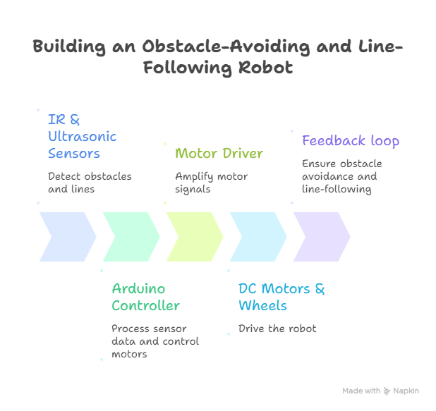
Description: Sensors feed real-time information to the Arduino, which processes it and sends PWM signals to the motor driver. Motors respond to control signals, allowing the robot to move and adapt to the environment.
4. Step-by-Step Assembly
1 – Chassis Assembly
- Attach wheels and motors to chassis.
- Mount motor brackets securely.
- Ensure motors are aligned for straight motion.
2 – Motor Driver Connection
- Connect DC motors to motor driver outputs.
- Connect motor driver input pins to Arduino digital PWM pins.
- Connect motor driver power supply separately from Arduino to avoid voltage drops.
3 – Sensor Installation
- Mount IR sensors in front for line detection.
- Mount ultrasonic sensor at the front for obstacle detection.
- Ensure sensors are properly aligned for accurate detection.
4 – Microcontroller Wiring
- Connect sensors to Arduino analog/digital pins.
- Connect motor driver input pins to Arduino PWM pins.
- Connect power supply and ground for all components.
5 – Programming
- Load Arduino IDE and write the following logic:
- Read IR sensor values.
- Read ultrasonic sensor distance.
- Compute motor PWM signals based on sensor input.
- Control motors to follow line and avoid obstacles.
6 – Testing
- Place robot on a test track.
- Observe line-following and obstacle avoidance.
- Fine-tune sensor thresholds and motor speeds.
5. Sample Arduino Logic Overview
if (ultrasonic_distance < safe_distance) {
stop_motors();
turn_robot();
} else if (IR_left detects line && IR_right detects line) {
move_forward();
} else if (IR_left detects line) {
turn_left();
} else if (IR_right detects line) {
turn_right();
}
Note: CuriosityTech.in provides full Arduino code and wiring diagrams for this logic, making it beginner-friendly.
6. Practical Tips
- Start Small: Use simple two-wheeled robots before multi-wheel or complex robots.
- Calibrate Sensors: Adjust IR and ultrasonic thresholds to match environment.
- PWM Tuning: Adjust motor speed for smooth movement and minimal overshoot.
- Test Incrementally: Test each subsystem (motors, sensors) separately before integrating.
- Use Simulation: Test code virtually using Gazebo or V-REP to reduce hardware errors.
7. Advanced Project Extensions
- Add Raspberry Pi for Vision: Use a camera to detect objects or colors.
- Implement PID Control: Improve line-following accuracy.
- Wireless Control: Add Bluetooth/Wi-Fi modules for remote control.
- Autonomous Navigation: Integrate LiDAR for mapping and SLAM algorithms.
Diagram Idea: Extended architecture showing Arduino controlling motors, Raspberry Pi handling vision processing, and sensors feeding combined data for autonomous navigation.
8. Learning Outcomes
After completing this project, learners will:
- Understand robot hardware assembly.
- Be able to interface sensors and actuators with microcontrollers.
- Implement basic control algorithms for line-following and obstacle avoidance.
- Develop hands-on problem-solving and debugging skills in robotics.
- Gain confidence to tackle more advanced robotics projects.
Conclusion
Building your first mobile robot is a foundational experience in robotics, integrating sensors, actuators, embedded systems, and control logic. By following structured tutorials and using guidance from Curiosity Tech, learners can transform theoretical knowledge into practical robotics expertise, paving the way for advanced projects like autonomous drones, robotic arms, and AI-enabled robots.